
 EN




What Heat Recovery Design Should an Energy Saving PVC-O Pipe Extrusion Line Adopt?
Heat recovery is often discussed as if one add-on can reduce the utility bill of any PVC-O plant. In practice, an energy saving PVC-O pipe extrusion line manufacturer should begin with the thermal map of the whole process: extrusion, conditioning or reheating, biaxial orientation, cooling, and the plant services around them. A better question is not “where is the hottest surface?” but “which heat stream is stable, clean enough to exchange, and needed elsewhere at the same time?”
From a PVC-O extrusion process consultant’s viewpoint, the answer also has to protect pipe quality. PVC-O production links a thick-wall PVC extrusion stage with a later heating and orientation stage. Temperature uniformity, pressure stability, cooling conditions, and accepted output all matter. A heat-recovery loop that disturbs those conditions can look efficient on a meter while creating scrap, unstable dimensions, or extra operator intervention.
Start with an energy boundary, not a recovery device
Before choosing hardware, define the calculation boundary for the energy saving PVC-O pipe extrusion line manufacturer project. Record electrical input to the extruder drives, barrel heating, orientation heating, cooling pumps, chillers or cooling towers, compressed air if used, and any ventilation equipment that serves the line. Divide the result by accepted pipe mass or by accepted pipe length for a defined diameter and wall class. Rejects, start-up material, and off-spec runs should be visible in the record rather than hidden in an average.
This is particularly important for a low energy PVC-O pipe production process. A lower kW reading at one cabinet does not prove lower energy per accepted pipe. Throughput, stabilization time, pipe geometry, resin formulation, ambient water temperature, and the share of recycled cooling water can all change the denominator. Establishing this baseline gives the engineering team a way to judge whether recovered heat is actually useful.
Locate the recoverable heat by temperature and timing
Most candidate streams fall into three groups. The first is warm cooling water leaving barrels, gearboxes, hydraulic circuits, calibrating equipment, or other controlled cooling zones. The second is warm air exhausted from guarded or conditioned areas. The third is heat rejected by a chiller or heat-pump condenser. Each stream needs a different check for temperature level, contamination risk, flow stability, maintenance access, and coincidence with the demand for heat.
Warm water is usually easier to manage than humid exhaust air because a closed secondary loop can isolate process water from a heat exchanger. Yet it is not automatically present in the system for recovery. If cooling-water temperature is tightly controlled to protect melt behavior or orientation conditions, extracting additional heat may increase chiller load elsewhere. Map supply and return temperatures, flow rates, control valves, and seasonal changes first. Then calculate the recoverable duty from measured conditions rather than using a catalogue estimate.
Match the source to a realistic heat sink
The strongest designs connect a stable source to a nearby, low-temperature demand. Possible sinks may include incoming make-up water preheating, space heating in suitable seasons, wash-water preparation, or a heat-pump evaporator circuit. The sink must be confirmed locally; it should not be assumed from another plant. If the available source is only mildly warm, a heat pump may raise its usefulness, but the added compressor energy and service requirements belong in the same energy balance.
For an energy saving PVC-O pipe extrusion line manufacturer, it is usually more practical to prioritize heat that can be used continuously during production than to pursue a high-temperature source that appears only during warm-up. A simple demand-duration chart—source temperature and flow on one axis, usable demand on the other—helps show whether a buffer tank, a bypass, or no recovery equipment is the sensible choice.
Protect the PVC-O process before claiming an energy result
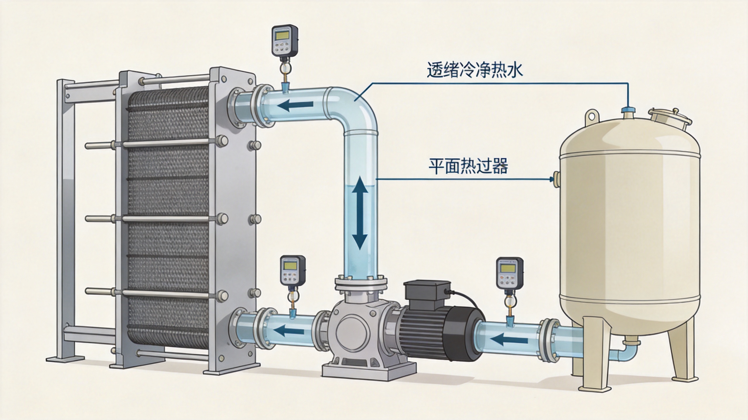
PVC-O pipe performance depends on controlled thermal history and orientation. Therefore, the heat-recovery design should be hydraulically and operationally separated from critical process-control loops. Use a secondary circuit, suitable heat exchangers, temperature sensors on both sides, isolation valves, filtration where the water quality requires it, and a bypass that keeps production cooling within its approved setpoint. The line controls should retain priority over any utility heat demand.
During design review, ask what happens if the receiving circuit is unavailable, the heat exchanger fouls, demand suddenly drops, or a pump trips. The response should leave the line able to return to its normal cooling arrangement without a prolonged quality adjustment. It is also worth deciding who will verify the result: production can review pipe appearance, dimensions, and scrap; maintenance can review fouling and alarms; engineering can compare the accepted-output energy record.
Use the low energy PVC-O pipe production process as a system, not a single component
A low energy PVC-O pipe production process begins with stable extrusion and continues through orientation and cooling. Heat recovery works alongside, rather than instead of, good screw selection, drive loading, insulation, water management, start-up practice, and control tuning. For example, a cleaner water circuit may preserve heat-exchanger performance, while better scheduling may align a useful heat sink with the line’s production hours. Neither point supports a fixed saving percentage without site measurements.
BECHTON works with PVC-O turnkey line discussions in the 110–630 mm range for global water-infrastructure applications. For a project in that range, the design conversation should start with the intended pipe sizes, resin and formulation conditions, production schedule, available cooling-water circuit, local climate, and any existing demand for low-grade heat. Those inputs determine whether a compact exchanger, an isolated recovery skid, a buffer arrangement, or a heat-pump-assisted loop has a defensible role.
A practical design sequence
- Measure the baseline: log power, temperatures, flows, throughput, rejects, and operating hours for representative products.
- Screen each heat stream: identify temperature range, cleanliness, variability, control sensitivity, and access for maintenance.
- Confirm the heat sink: verify its temperature requirement, timing, hygiene or water-quality restrictions, and seasonal demand.
- Separate critical loops: keep production cooling under its own control logic, with exchanger isolation and a safe bypass.
- Trial and verify: compare energy per accepted output before and after the change while checking pipe quality and downtime records.
Questions to put to an energy saving PVC-O pipe extrusion line manufacturer
- Which cooling and heating circuits are included in the line scope, and which remain site utilities?
- What temperature and flow data can be logged at the proposed recovery connection point?
- How is the production cooling setpoint protected if heat demand changes?
- What maintenance access, filtration, and bypass arrangement are included?
- Can the acceptance review compare specific energy against accepted pipe output for the agreed products?
Those questions keep the discussion grounded and help distinguish a useful recovery opportunity from a concept that merely moves heat without lowering the plant’s total energy demand.
Choose the design that fits the operating evidence
The appropriate heat-recovery design is the one that matches measured low-grade heat, a verified concurrent demand, and the PVC-O line’s quality controls. Start with a measured thermal map, favor isolated and controllable loops, and judge the outcome by energy per accepted output rather than by a single component reading. With that approach, an energy saving PVC-O pipe extrusion line manufacturer can evaluate recovery options without making assumptions that the plant data cannot support.