
 EN




What Melt Pressure Protection Should a High Speed PVC-O Pipe Production Line Install?
Installing melt-pressure protection on a high speed pvc-o pipe production line is not a matter of adding a gauge and choosing an alarm number. It is a process decision connecting the extruder, melt path, die, orientation section, controls, and the commissioning record. For a pipe manufacturer evaluating a high speed pvc-o pipe production line, the useful question is where a pressure signal is representative, reliable, and actionable.
From a pipe-manufacturing buyer’s perspective, the installation must be reviewed alongside pipe size, PVC formulation, output target, die arrangement, and the plant’s maintenance practice. BECHTON supplies turnkey PVC-O pipe production lines for water-infrastructure projects in the 110–630 mm range, but each melt-pressure arrangement still needs engineering confirmation against the actual machine configuration. This article is a practical checklist, not a substitute for the instrument supplier’s installation instructions or the line’s electrical drawings.
Why melt pressure belongs in the protection plan
On a high speed pvc-o pipe production line, melt pressure is a process indicator rather than a stand-alone quality result. A rising trend can point to a restriction, a temperature imbalance, a screen-change condition, or a change in material response. A falling trend can signal a feed or melt-delivery issue. The control team should interpret the signal with melt temperature, screw speed, motor load, haul-off behavior, and pipe geometry instead of reacting to one number in isolation.
PVC-O manufacturing also has downstream orientation-related stages, so stable melt delivery is useful before operators begin judging the finished pipe. ISO 16422:2014 covers requirements for PVC-O pipes and joints used in piping systems; it does not prescribe the location or setpoint of a melt-pressure transmitter. That distinction matters. The pressure-protection design must support the installed process while the quality plan verifies the finished product against the applicable specification.
Choose the measurement point before selecting the alarm logic
A high speed pvc-o pipe production line normally benefits from locating the primary measurement point where the melt is adequately homogenized and the signal reflects the restriction that the line needs to manage. General instrument guidance commonly places a transmitter ahead of the screw where the polymer has reached a stable melt state and shear stress is lower. The exact port location, adapter geometry, and sensor type must be approved by the extruder and sensor suppliers.
Do not treat a convenient threaded opening as automatically suitable. Review whether the sensing diaphragm will see flowing melt rather than a stagnant pocket, whether the installation permits safe removal, and whether the cable route is clear of heat, vibration, and mechanical damage. Confirm the pressure range and temperature capability from the instrument documentation; do not copy another plant’s setpoint or range. On an installed PVC-O line, a reading that is stable but poorly located can create false confidence.
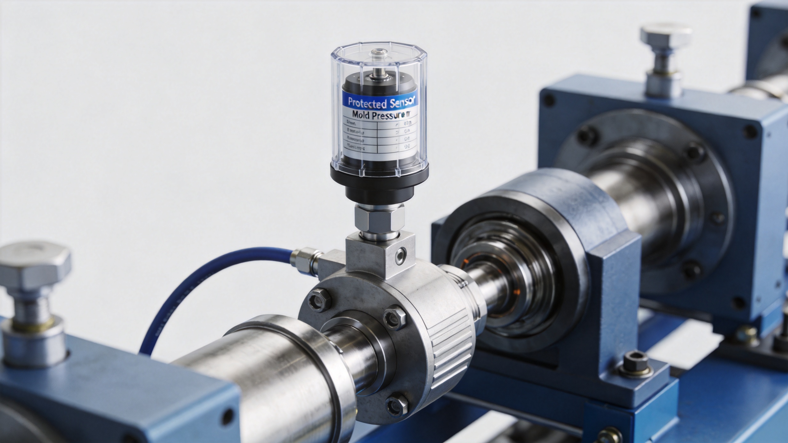
Installation checklist for the sensor and mechanical connection
- Confirm the process boundary. Identify the extruder, adapter, screen changer if fitted, and die sections covered by the pressure point. Mark the port on the approved process drawing for the line.
- Inspect the pressure port. Check thread condition, seating surface, depth, cleanliness, and the required installation equipment. Keep the sensor’s protective cap in place until immediately before fitting, following the sensor manufacturer’s procedure.
- Use the approved torque and sealing method. Excess torque, contamination, or an incompatible connection can damage the diaphragm or distort the reading. Record the part number, installation date, and technician in the commissioning file.
- Protect the cable run. Provide strain relief, appropriate shielding and grounding as specified by the controller and sensor documentation, and a route that supports inspection. Label the signal at both ends.
- Plan access. A high speed pvc-o pipe production line should allow trained personnel to inspect or replace the device without improvising around hot surfaces or moving equipment.
Build protection in layers: indication, alarms, and controlled response
The pressure input should first be visible to operators as a trend, not only as a single display value. Establish a normal operating band during trials using a defined formulation, temperature profile, output rate, and die configuration. Then agree how deviations are handled. A low-level warning can ask for an operator check; a higher alarm can initiate a controlled response defined by the machine’s safety and process engineers. The response might involve reducing output, holding a changeover sequence, or bringing the line to a managed stop, depending on the verified design.
For this type of PVC-O line, alarm delays and interlocks deserve as much attention as setpoints. A nuisance trip disrupts production; a delayed reaction can allow an abnormal condition to persist. Use time-stamped trials to determine how the pressure trend behaves during warm-up, normal changes, and planned stoppages. Strictly speaking, no generic pressure number can be transferred safely from one installed line to another because screw design, compound, temperature, and flow path affect the signal.
Connect pressure protection to the high speed PVC-O extruder
The high speed pvc-o extruder and its melt path determine whether the measurement is meaningful. Before commissioning, make a cause-and-effect table that maps pressure warnings to verified checks: material feed, barrel-zone status, screw speed, screen condition, die temperature, and downstream line status. This keeps the team from treating the transmitter as the sole answer to every process deviation.
At start-up, heat the system according to the approved procedure, zero or verify the instrument only when the process condition permits it, and log baseline values at several agreed output points. During the first production runs of the commissioned line, compare the live trend with actual operator observations and maintenance findings. If the sensor shows drift, noise, or an implausible response, isolate the reason before changing alarm thresholds.
Commissioning records that make later troubleshooting easier
A usable handover package for the production line should include the transmitter model and range, port location, wiring reference, calibration or verification record, alarm philosophy, approved setpoints, response matrix, and responsible roles. It should also state the conditions under which the baseline was captured. If acceptance documentation is not agreed early, similar equipment can later be assessed against different criteria.
Review the records after the line reaches stable output and again after the first planned maintenance interval. This is especially helpful when the site changes pipe diameter, formulation, or throughput. The goal is not to claim a universal pressure target; it is to keep the pressure-protection loop traceable as the production line evolves.
Questions to settle with the line supplier
- Which melt section does the installed port represent, and why was that location selected?
- Which sensor range, diaphragm configuration, connector, and installation torque are approved for this line?
- What process data is shown with the pressure trend, and who approves the normal operating band?
- What happens at each warning and alarm level, including restart conditions?
- Which documents, spare parts, and verification steps are included in the handover?
For an international water-pipe project, market location is only a starting point; configuration must return to pipe diameter, material, local electrical conditions, and site process requirements. When those inputs are documented, melt-pressure protection becomes a practical part of commissioning a high speed pvc-o pipe production line rather than an isolated accessory.